- Sea Ray
- Sea Ray Boats
- Cabin Cruisers
- I have a 2000, 340 Sundancer that...
- Subscribe to RSS Feed
- Mark Topic as New
- Mark Topic as Read
- Float this Topic for Current User
- Bookmark
- Subscribe
- Mute
- Printer Friendly Page
I have a 2000, 340 Sundancer that...
- Mark as New
- Bookmark
- Subscribe
- Mute
- Subscribe to RSS Feed
- Permalink
- Report Inappropriate Content
06-23-2022 08:37 PM
I have a 2000, 340 Sundancer that has two small cabinets/lockers on the port side, aft deck. I need to remove the interior lining panels to gain access to the hull behind each. They are tightly fitted in the enclosure, and I cannot locate any screws that may be holding them in place. It seems that they are snapped in, but before I start to pry them out, I am seeking help as to how they are held in place. Thanks
- Labels:
-
Overnighter
- Mark as New
- Bookmark
- Subscribe
- Mute
- Subscribe to RSS Feed
- Permalink
- Report Inappropriate Content
06-24-2022 04:52 AM
- Mark as New
- Bookmark
- Subscribe
- Mute
- Subscribe to RSS Feed
- Permalink
- Report Inappropriate Content
06-24-2022 09:28 AM
- Mark as New
- Bookmark
- Subscribe
- Mute
- Subscribe to RSS Feed
- Permalink
- Report Inappropriate Content
06-24-2022 09:30 AM
- Mark as New
- Bookmark
- Subscribe
- Mute
- Subscribe to RSS Feed
- Permalink
- Report Inappropriate Content
06-24-2022 10:32 AM
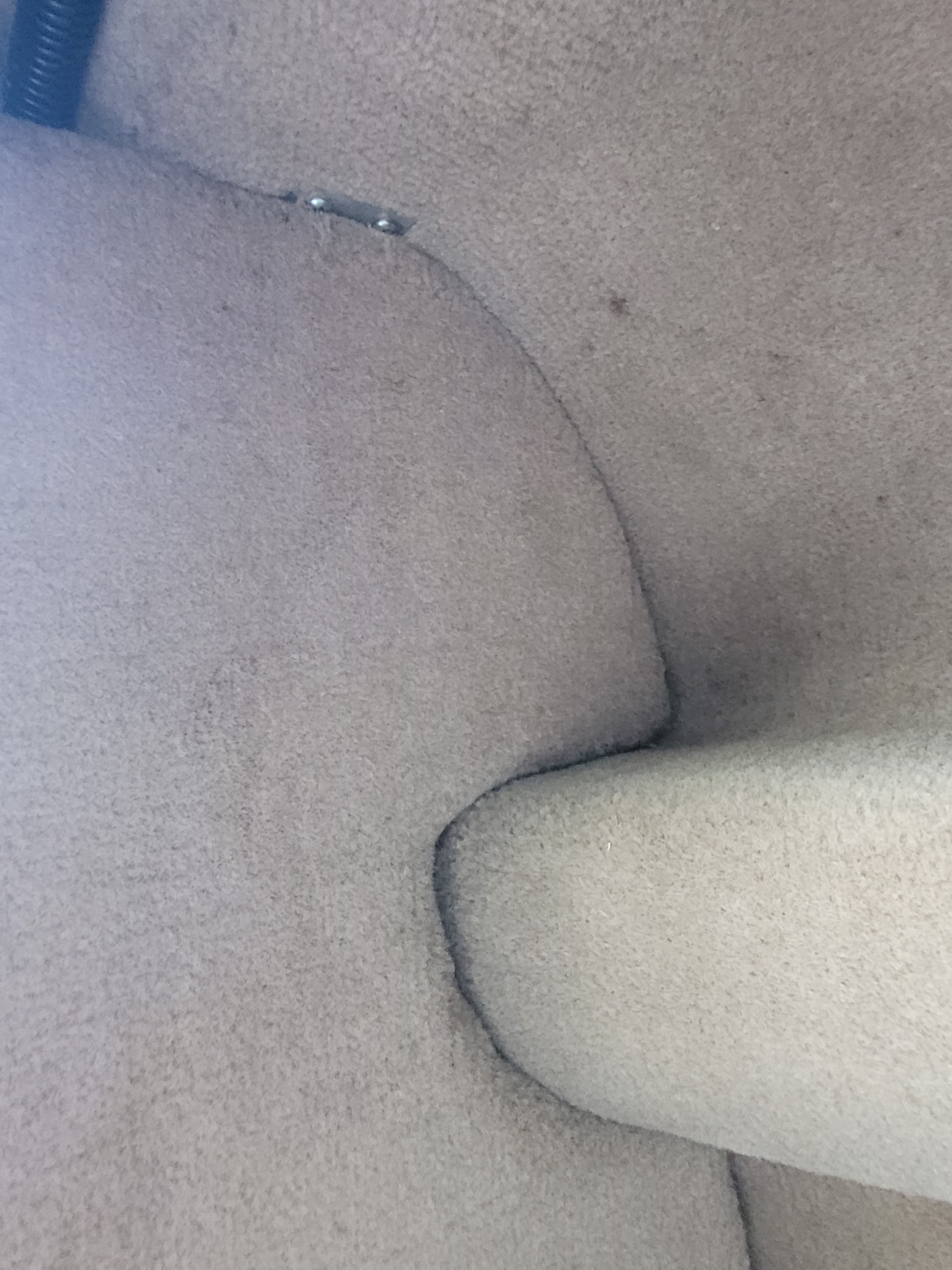
My speculation is that the screws used for assembling that cabinet exist on the back side, at the perimeter.
Remember the factory needed to assemble the boat, so there is some way for placing that cabinet into a boat w/ a hull, top side and cockpit.
Why not post an image further away?
This form permits posting one image per reply, or I use Flickr to host images, so I can drop as many image URL links per reply as desired.
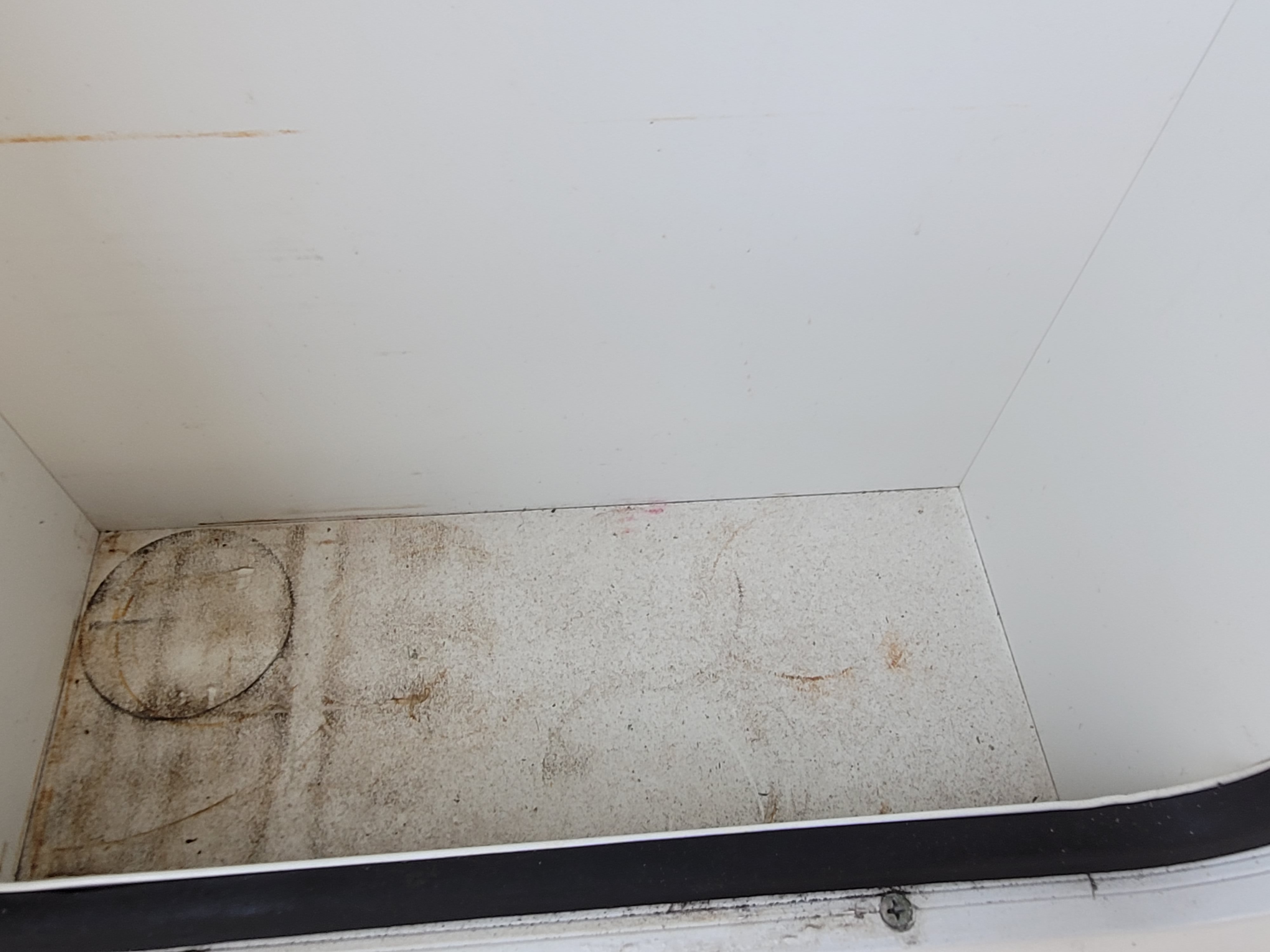
The existing image shows one large Philips head screw on the floor.
- Mark as New
- Bookmark
- Subscribe
- Mute
- Subscribe to RSS Feed
- Permalink
- Report Inappropriate Content
06-24-2022 10:35 AM
- Mark as New
- Bookmark
- Subscribe
- Mute
- Subscribe to RSS Feed
- Permalink
- Report Inappropriate Content
06-24-2022 12:11 PM
My speculation is that more similar attachment points exist around the perimeter. Is that correct? If so, what happens when those screws are removed? Is the panel detached?
- Mark as New
- Bookmark
- Subscribe
- Mute
- Subscribe to RSS Feed
- Permalink
- Report Inappropriate Content
06-24-2022 12:47 PM
- Mark as New
- Bookmark
- Subscribe
- Mute
- Subscribe to RSS Feed
- Permalink
- Report Inappropriate Content
06-24-2022 01:01 PM
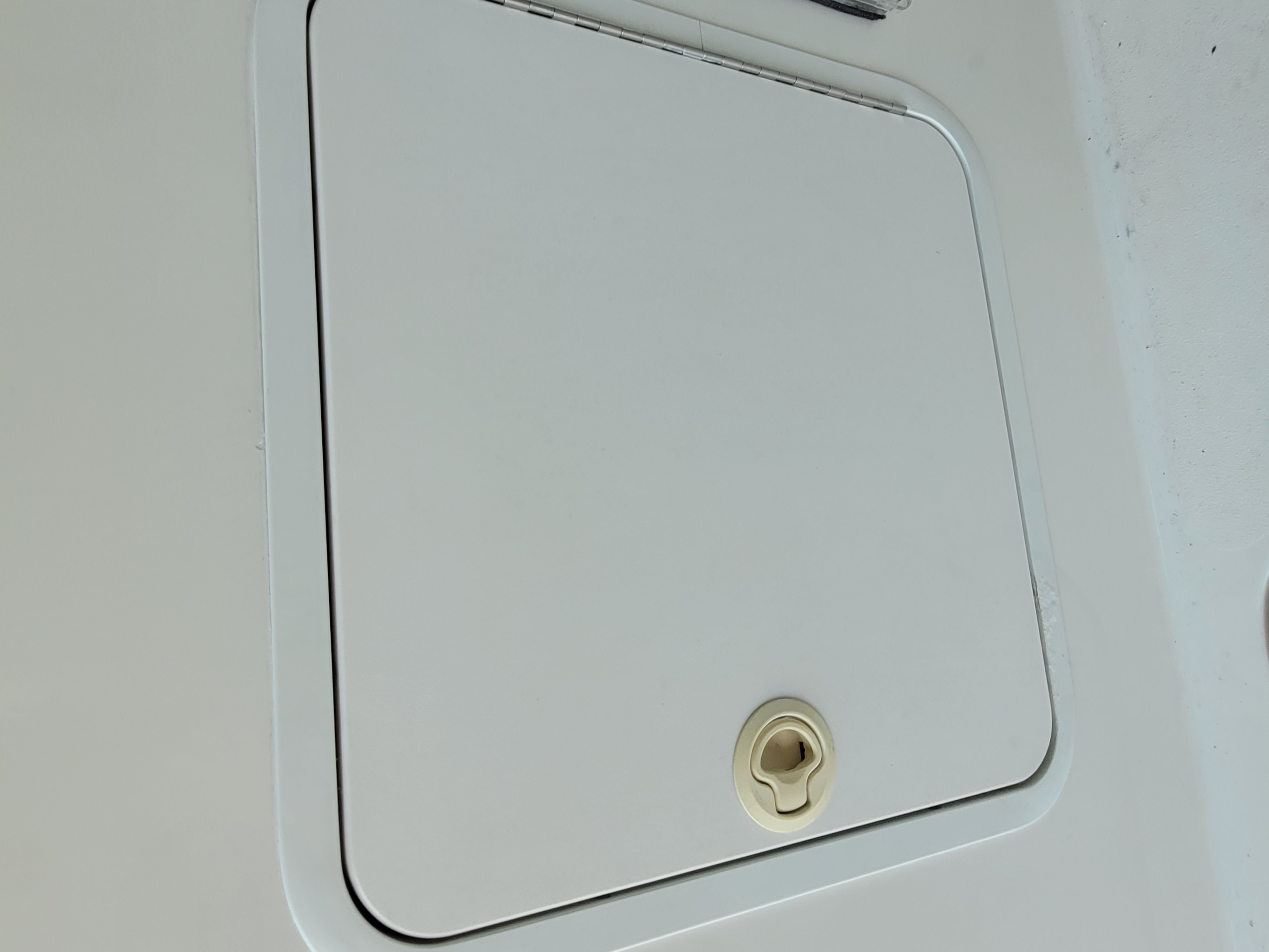
Note that while the accessible cabinet panel doesn't require removal, it might need to come out if an obstructing part must move through the opening created by removing the part.
- Mark as New
- Bookmark
- Subscribe
- Mute
- Subscribe to RSS Feed
- Permalink
- Report Inappropriate Content
06-24-2022 04:32 PM
- Mark as New
- Bookmark
- Subscribe
- Mute
- Subscribe to RSS Feed
- Permalink
- Report Inappropriate Content
06-24-2022 04:38 PM
- Mark as New
- Bookmark
- Subscribe
- Mute
- Subscribe to RSS Feed
- Permalink
- Report Inappropriate Content
06-24-2022 05:27 PM
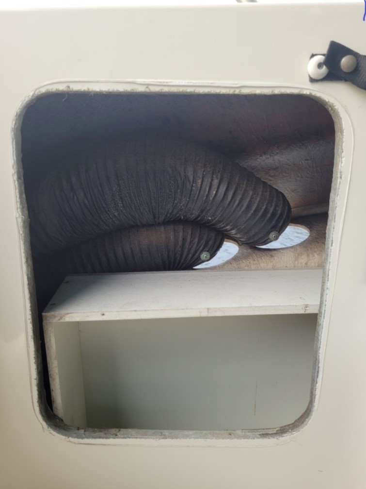
Thanks very much for the detailed update and image. It is very helpful.
It should be possible to carefully massage the hose back into shape, because of the internal spiral wire reinforcement.
As was mentioned, when I did my hoses it was a two person project, with someone next to the hull exterior manipulating parts while my contorted body worked within the engine room. Yours appears to have better access, from the cockpit.
- Mark as New
- Bookmark
- Subscribe
- Mute
- Subscribe to RSS Feed
- Permalink
- Report Inappropriate Content
06-25-2022 06:05 AM
- Mark as New
- Bookmark
- Subscribe
- Mute
- Subscribe to RSS Feed
- Permalink
- Report Inappropriate Content
06-25-2022 06:44 AM
- Mark as New
- Bookmark
- Subscribe
- Mute
- Subscribe to RSS Feed
- Permalink
- Report Inappropriate Content
06-25-2022 09:03 AM
The standard parts are too long, so I needed to cut off about 1" per side, to match the factory parts that were also modified, by Sea Ray, to work in the application.
The standard and modified parts are shown in one image. The best I can provide is the eyeball measurement from the images.
One side, with the factory vent flange and the other side w/ the additional flange is shown in the other image.
https://live.staticflickr.com/65535/50235472627_888cb87acc_c.jpg
https://live.staticflickr.com/65535/50235258716_991bde4276_c.jpg
- Mark as New
- Bookmark
- Subscribe
- Mute
- Subscribe to RSS Feed
- Permalink
- Report Inappropriate Content
06-25-2022 09:08 AM
The existing OEM cutout locations are the maximum size that is covered by the curved oval panel. The new hull cutouts are also the maximum size that is also covered by that curved oval panel.
- Mark as New
- Bookmark
- Subscribe
- Mute
- Subscribe to RSS Feed
- Permalink
- Report Inappropriate Content
06-25-2022 04:09 PM


- Thruster battery location 2016 400da in Sport Yachts/Yachts
- Breaker panel courtesy light in Cabin Cruisers
- Kholer generator on Sundancer in Sport Yachts/Yachts
- 2001 Sea Ray 290 Sundancer - looking for step-by-step operating guide in Sport Yachts/Yachts
- Engine room door on a da220 sundancer 1990 in Sport Yachts/Yachts
